
 Another home security system ensures peace of mind. Based on the MC13192 SARD board, the system uses wireless sensors to monitor the garage door, indoor and outdoor temperatures (for maintaining heat/air conditioning systems and water pipes), and the water level in the sump pump hole. The user can call home and enter a security code to receive a status report about the conditions in his house. The project builded by Carl Smith
20091030
Home Security System Alarm
Another home security system ensures peace of mind. Based on the MC13192 SARD board, the system uses wireless sensors to monitor the garage door, indoor and outdoor temperatures (for maintaining heat/air conditioning systems and water pipes), and the water level in the sump pump hole. The user can call home and enter a security code to receive a status report about the conditions in his house. The project builded by Carl SmithPIC Project : Alarm Security System
 This Alarm Sytem is based on two PIC12C508 (one is used in transmitter and the other one in the main unit). The following PICs are supported: 12c508, 12c509, 12c508a, 12c509a, 12ce518, 12ce519, 12f508, 12f509, 16f84 and 16f84a. Transmitter uses infra red beam to send code name to main unit. The commands are:
* Arm/Disarm
* Silent Arm/Disarm
* Weak battery in transmitter
It implements the folowing features:
* IR remote keyless system
* 72 bits transmission length (64bits password, 4bit CRC, and 4bits for commands)
* Arm/Disarm
* Immobilizer
* Two stage sensors, door and shock sensor trigger inputs
* Locking/unlocking of doors
* Normal/Silent modes
* Inside zone intrusion memory
* Transmitter low battery indication
This system is a perfect solution for unidirectional remote keyless entry systems and access control systems. Such system may be implemented in:
* Automotive alarm systems
* Automotive immobilizers
* Gate and garage door openers
* Burglar alarm systems
Download
Here you can find transmitter assembler code (updated on March 11, 2008) and a password.inc file. Don't forget to change processor type in MPLAB or you will get errors. I've added PIC16F84 family processors for debug. And also you can find main unit assembler code.
Schematic
Download Transmitter schematic, main unit schematic, IR Receiver schematic, IR Receiver Schematic Diagram (TBA2800 Based)
20091027
controller Port LED's (v0.1)
Ok since many have asked and wondered I decided to take what I did and write up a tutorial. PLUS i got together with another xbox-scene member, DrewB612, to add his way of doing it.
here goes:
First off get your supplies ready.
3mm LED of the desired color
3.1mm drill bit = 1/8" bit
a drill
wire around 26 gauge is good (warning i used 30 gauge and it didn't work.. so lower than 30)
150ohm resistor 1/4 watt
soldering iron (15w is best)
solder
wire stripper or a knife if u can handle yourself
Hot glue gun
OK so now we start.
My way is for all version, with or without daughter board.
WARNING!!! if you screw up your xbox because u tried this mod don't blame ME or anybody else but yourself.
So unscrew the controller port, unplug it and lay it on the floor so that the ports are facing down and the metal part is facing up. Drill a hole in the center of the back of each of the ports. I drilled mine a little lower just because the wires are high and i didn't feel like drilling them.

After the all the holes were done i soldered one wire to the the metal back of each controller port as in pic above.
Than that went to the negative terminal (the longer one) of the LED.
Than i stripped a pice of the red shielding from each of the red wires (about 3mm long) that come out from the daughterboard and go into the controller port. Than I soldered a wire to each of the exposed points and taped it over with electric tape.

The other end of that wire goes to a resistor (150ohm) and from the resistor it goes to the positive terminal of the LED.

After u taped all that up put in the LED into the 3mm hole and hot glue it into place.

Next bend the LED terminals back and get all the wires out of the way and stick the port back into place. Now plug it into the daughter board and voilá. reconnect everything and now u have controller Port LED's.
So here is what it looks like.


So thats my way of doing it. Here is how DrewB connected the power supply. (we used the same resistors, same wires, etc.-just different (to some, easier) way of connecting power. BUT if your xbox doesn't have a daughterboard than u have to use my method or u can wire it up to the mobo.. which i do not suggest and will not discuss here.
But he is the way to connect it to the mobo.

If u cant tell thats the back of the daughterboard :P You can use either the left point from each pair as ground or the metal case as i did.
Good Luck, and happy modding from mkollek! Any questions PM me. My nick is mkollek.
Thanks to DrewB for his input
Tutorial written by : mkollek
20091026
Light Sensing RF Transmitter
 This transmitter is very similar to the simplest RF Transmitter. The Different is the photoresistor placed in series with R1. This could be also a thermistor or other variable resistance sensor. The frequency of the tone that is transmitted varies with the amount of light falling on tha photoresistor.
L1 is 20 to 30 turn of 24 to 32 ga. Magnet wire close wound around a 1/8 to 1/4" diameter non-conductive form and tapped 1/3 or the way from one end. The tap is connected to the emitter of Q1.
The user should be able to pick up the signal from this transmitter on any regular FM or VHF receiver. By increasing the number of turns on L1, the RF frequency can be dropped down all the way into the AM broadcast band.
20091025
Microchip Technology Sets New Industry Standard
Microchip Technology Inc. announced full MPLAB® development tool availability to support today’s launch of the new PIC32 32-bit microcontroller family. The immediate availability of a broad and compatible suite of tools means that Microchip’s current customers can easily make the transition from 8- and 16-bit microcontroller development to 32-bit development. At the same time, designers new to Microchip will find a highly integrated 32-bit toolchain that sets a new industry standard for integration and ease of use. PIC32 tool support is available today from the free MPLAB IDE version 8.0, the MPLAB C32 C compiler (including a free evaluation version), the MPLAB REAL ICE™ emulation system and the MPLAB ICD 2 in-circuit debugger.

With 16 years of experience in the marketplace and full support for all PIC® microcontroller families, the MPLAB IDE is the tool of choice for the majority of Microchip’s customers. The free MPLAB IDE supports the PIC32 family’s advanced debugging features, such as hardware-based complex break points, trace debugging, as well as full project-management features for developing complex projects.

The MPLAB C32 C compiler (part # SW006015) is available now with a free Student Edition that supports 64 KB of compiled code, and a full edition that supports unlimited compiled code. The MPLAB C32 is fully integrated with the MPLAB IDE and select third-party IDEs. The compiler package includes an ANSI C compiler, assembler, linker and peripheral libraries for the PIC32 family. The peripheral libraries are API compatible with the MPLAB C30 C compiler that is used with Microchip’s 16-bit MCU and DSC families. The end result is highly optimized code for smaller, faster-running applications that are portable across Microchip’s 16- and 32-bit portfolios.

Microchip Switches to MIPS Core for PIC32
Last month, Microchip announced a new 32-bit microcontroller chip family, the PIC32. With this family, Microchip—a long-time player in 8- and 16-bit microcontrollers—is going after the 32-bit microcontroller market, and making a big change in architecture. Unlike Microchip’s earlier chips, which were based on the company’s proprietary processor architecture, the new family is based on the MIPS M4K core. PIC32 chips, which are currently sampling, will operate at up to 72 MHz, with pricing ranging from $2.95 to $5.30 in 10K quantities. A block diagram of the PIC32 is shown in Figure 1.

Of course, Microchip could have achieved the same effect by going with an ARM core (the relatively new Cortex-M3 springs to mind), which is what several of its competitors have done. According to Microchip, the company chose the M4K because it provided the best fit for deeply embedded applications—the best combination of power, performance, interrupt capabilities, code density, and potential future customizations. The M4K provides a co-processor interface, and also allows licensees like Microchip to define custom instructions. If Microchip decides to use custom instructions, however, they may compromise their ability to leverage some of the existing development infrastructure.
BDTI recently completed an evaluation of the MIPS M4K core, with a focus on assessing its signal processing features and capabilities. The M4K is not a DSP processor, but microcontrollers are increasingly called upon to do simple signal processing, so it’s useful to understand its capabilities in this area, and compare them to those of the Cortex-M3. Here are a few of the highlights of our evaluation.
The M4K core has more registers than the Cortex-M3 (32 vs. 16), and Microchip went one step further by configuring the core with an additional 32 shadow registers. More registers can mean more efficient software; they can be used, for example, to store more coefficients, parameters, and data values on-core, allowing instruction slots that would otherwise be needed for memory transfer operations to be used to increase the throughput of computation operations. But the Cortex-M3 has an advantage in multiplications—it can do single-cycle 32x32 multiplication, which the M4K cannot (it requires at least 2 cycles). The M4K can, however, do single-cycle 32x16-bit and 16x16-bit multiplies.
Compared to Microchip’s 16-bit, DSP-oriented dsPIC family, the PIC32 may be somewhat faster on typical DSP code. The newer chip can perform the same number of 16x16-bit multiplications per cycle (one) and executes at roughly twice the clock speed of current dsPIC chips. However, the dsPIC includes DSP-oriented features that the M4K lacks, such as support for saturation and rounding, hardware looping, and specialized address modes. Cumulatively, these features can have a significant impact on DSP performance—both in terms of speed and energy efficiency. It will be interesting to see whether Microchip ends up licensing a higher-performance MIPS core (such as the DSP-oriented 24KE) for future DSP-oriented chip families, or adding its own DSP-oriented custom instructions, as it did with the dsPIC.
In its press release, Microchip characterizes the PIC32 as being “software compatible” with its earlier chip families, but this characterization is slightly misleading. The chips are software compatible if you’re working in C (which Microchip expects most of its customers to do) but because the new chip family is based on a different instruction set architecture, any legacy assembly code will need to be rewritten.
The “software compatibility” Microchip is talking about is more of a system-level compatibility. Because the new chips use the same peripherals as the older chips, any C code written to use specific peripherals will work on the new chips, and Microchip provides peripheral libraries with compatible APIs. In addition, the new family is supported by the same tool chain (MPLAB) as all the other Microchip MCUs. In fact, according to Microchip, tool chain compatibility was another reason they chose the M4K; MIPS had placed the M4K compiler in the GNU compiler base, and Microchip was already using GCC for its 16-bit MCUS—thus making for an easier integration with Microchip’s existing tool chain.
Microchip’s decision to move to a licensable core—and to the M4K in particular—appears to be a reasonable one. Time will tell if Microchip’s customers will make the jump with them.
PIC Low Cost USB-CAN Distributed Motion Control System
 This project presents high performance distributed motion control system at extremely low cost. Rapid prototyping of multi-axis designs is often required during the development of automation equipment. One can use centralized controls with PC motion control cards, external amplifiers, and a tangle of wires, or utilize existing high cost distributed motion control system with RS485, Ethernet, or one of the fieldbuses (DeviceNet, CANOpen, Profibus, etc.). With the use of highly integrated microcontrollers, such as the PIC18FXX8, and power devices like the Allegro A3977/A3959, a very small and inexpensive system was developed.
Download
document and schematic
SPOT : AVR Wireless Flash Trigger

The SPOT (strobist-project-opensource-trigger)is a remote flash trigger radio transceiver. It lets you adjust and trigger off-camera flashes remotely. It has two modes of operation: First, As a transmitter it sits on the hot shoe of a camera and forwards electrical flash trigger signals from the camera to slave flashes via radio. Secondly, As a receiver it is connected to a small hot shoe ("system") flash. The project use microcontroller AVR ATmega 8L as main controller.
Download :
Documentation and source
PIC Wireless Networks Wifi (Hotspot) Detector
 This wireless detector project allows you to sense the presence and relative signal strength of wireless hotspots. It is "always on" and communicates the presence and signal strength of an in-range hotspot by way of sequences of pulses - like a heartbeat you can feel. The stronger and faster the "heartbeat", the stronger the wireless signal detected.
This project consists of a microcontroller PIC 12F629, some custom interface electronics, a small vibe motor, and an off-the-shelf Wi-Fi detector from D-Link. The microcontroller periodically "presses" the button on the detector to initiate a reading. The microcontroller "reads" the output from the detector indicator LEDs and uses this as the basis for pulsing out a signal on the vibe motor, which the wearer can feel.
tag : wireless networks, hotspot detector, Wi-Fi strength signal indicator src
PCM2706 High Fidelity USB Soundcard or USB Headphones
 This is a high fidelity external USB Soundcard / USB Headphones project that can be built for your PC or Mac. It is based on the latest PCM2706 IC which functions as a high quality, crystal clear 16-BIT Stereo DAC. It is a single chip digital-to-analog converter that offers two D/A output stereo channels, digital S/PDIF output and requires very few external components. PCM2706 includes integrated USB 1.0 & USB 2.0 compliant interface controller and it is conveniently powered directly from USB connection. PCM2706 is a USB plug-and-play device and does not require any driver installation under Windows XP and Mac OSX
20091023
dsPIC 33F128MC706 NUE-PSK Digital Modem

PSK31 is one of the latest communications modes to capture the interest of hams worldwide. Its inherent ability to dig out low, near-inaudible signals is ideally suited for low power QRP enthusiasts. The PSK31 digital modem engine, however, requires intense DSP processing that is only commonly available in PC sound card. Thus the PSK operator desiring portability for field operation is locked into using a laptop computer as a controller, which results in a cumbersome station.
This project shows you design and construction of a standalone, battery-operated digital modem using a Microchip dsPIC microcontroller. The project includes a character display for transmit and receive text data, and a graphic display showing band spectrum and tuning indicator. Using GPL open source software, the modem can be homebrewed for less than $50 parts cost. When coupled with an SSB-capable transceiver or with a popular PSK-xx transceiver board from Small Wonder Labs, you too can have an effective portable PSK31 station.
© George Heron and Milton Cram
Download
Project documentation
tag : Digital Modem, PSK, DSP, MCU dsPIC33F128MC706, Communication
Atari joystick gets second bloom as TV remote
Perhaps I misremember, but wasn’t the Atari joystick a little stubborn to move? No matter, Hacked Gadgets have decided to make one into a remote control, where the only giveaways that all is not as it was are a couple of IR LEDs sticking out.


They’ve put together a whole tutorial about how they put it together, which makes it a potentially good starter project if you’re interested in making your own, but it also opens up the floodgates for a number of repurposed-as-remote projects. What would you like to see serving as control for your TV?

20091022
AVR General Purpose Infrared Remote Control Receiver with RS232 Output
 This Infrared Remote Control Receiver can receive signals transmitted by an infrared remote control that uses the NEC protocol, or similar, with 32 bits of data. The received signal is converted to ASCII and sent on the RS232 protocol 19200bps, no parity, 8 data bits, 1 stop bit. The power is drawn directly from the serial port of your PC, as long as you activate the RTS and DTR lines, to test the circuit you can use the HyperTerminal program standard on Windows.
Download : Source Code and schematic
AVR Remote control for TV (Salora)

This is a AT90S2313 microcontroller project based which has function to turns ON the TV-channel 5 - at programmed time (triggered by alarm clock without buzzer). This electronic project use Infrared remote control with fixed code to turn on a TV Salora to a set timetable. The project designed by Emilio Pietro Giovanni.
Download
source code and schematic
Download
source code and schematic
RC Pulse to PWM Converter Project
 This Project describes an AVR chip and software that converts two easily formed R/C pulse signals and converts them into a PWM signal suit for driving small motors. This will be good solution for common problem for hobby robotics when controlling the drive level to a motor. As many hacked R/C servo's are used have poor control range. And many micro-controllers don't have built in PWM or the PWM is very slow and makes for lots of motor buzz.
 The value of this AVR software application is that one can interface the output signals of the AVR chip to a wide variety of H-Bridge driver chips with a current capacity from 600ma to 5+ amps. Or, it could drive a discrete FET bridge for even higher capacities. The software runs on an Atmel AT90S1200 chip with a 16mhz clock. The project designe by Larry Barello.
Download :
User Guide (doc), schematic and source code
Download :
User Guide (doc), schematic and source code
Smartphone AVR DTMF Remote Control

This project based on Microcontroller AVR ATtiny 2313 and SmartPhone as main part. The project can controls 3 relays by DTMF sounds emitted by a Smartphone. Emilio, the designer, said that this project useful for controlling, for example a rover, using relay as motor power switches.
The Smartphone (with Windows Mobile 6 OS) can run as web server with capture ability and send the picture to the client via internet. Other features of this circuit is the Smartphone can also moved and controlling motors with his speaker, emitting the correct dial tones in relation to GET requests from internet client. It's not necessary to make any connection from the phone to the circuit, because the phone connects "wireless" using the sound.
You can download test program written for smartphone WM6, schematic, and hex file here.
PIC LCD Oscilloscope for Spectrum Analyzers
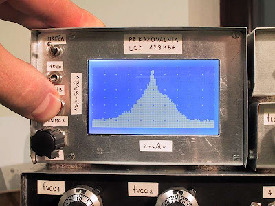 This is simple and inexpensive LCD oscilloscope for spectrum analyzer display. The project use PIC 16F876A as main processor. Although a small LCD screen is not as good as analog oscilloscope, a LCD oscilloscope may be very useful in field measurements, for battery operation or you need different measurement at the same time along with oscilloscope.
The 80dB scale of this LCD oscilloscope can be adjusted with the two trimmers providing the reference voltages to the A/D converter. The operation of the LCD oscilloscope is slightly different between the 80dB mode and the 40dB mode. In the 80dB mode, the trace is always visible and saturates on the bottom or top of screen. In the 40dB mode, the trace runs out of the screen and only the central part of the original 80dB scale is displayed. This project designed by Matjaz Vidmar.
Download
Source code, documentation and schematic
Download
Source code, documentation and schematic
PIC-Based Laser Light Show Controller

Here is a laser light show utilizing a ds-PIC controller as an arbitrary waveform generator (ARB) created by professor mark. The controller allows vector patterns to be either stored in flash (program) memory or uploaded from a PC in a vector format. Analog output, via two 14-bit DACs, is fed to a commercial analog driver board and two high-speed galvo scanners.
AVR Project Wii Conductor

This AVR project is a simplified implementation of Wii-Music, utilizing a Nintendo Wii Remote (“Wiimote”) to play a gesture-based music game with the player as a virtual music conductor. The project exploited two of the Wiimote’s features: its wand-like shape and the embedded 3-D accelerometers. By interfacing between Microcontroller AVR ATmega 644 and Wiimote, the project able wirelessly transmit motion gestures and button pushes to the MCU. The MCU uses these inputs to create sound by means of Direct Digital Synthesis (DDS).
Arduino Autopilot Control

ArduPilot is a full-featured autopilot based on the Arduino open-source hardware platform. It is a custom PCB with an embedded processor (ATMega168) combined with circuitry to switch between RC control and autopilot control (that's the multiplexer/failsafe, otherwise known as a "MUX"). This controls navigation (following GPS waypoints) and altitude by controlling the rudder and throttle. These components are all open source. This autopilot is fully programmable and can have any number of GPS waypoints (including altitude) and It uses infrared (thermopile) sensors for stabilization and GPS for navigation.
 tag : Arduino project, Auto Pilot Control, Embedded project src
Robot Project : Nickel-O-Matic
 Nickel-O-Matic was designed to entertain and provides gratuitous mechanical motion rather than efficient production. Nickel-O-Matic uses inkjet technology to print a custom message on both sides of 1-1/2" diameter blank wooden nickels. The robot uses a BASIC Stamp 2 to control much of the mechanical movement and a Propeller Chip to control the Inkjet system. The two controllers run a total of four hobby servos, three stepper motors, one DC motor, one DC vacuum pump, one inkjet head, and five IR sensors.
Mike Davey, the designer, said that the system was built as a number of modules to make design and trouble shooting simpler. The most complex of the modules is the inkjet system. At the center of the inkjet module is a spindle that rotates the wooden nickel under the inkjet head. This spindle is turned with a stepper motor and allows for repeatable placement of the nickel under the inkjet head. The spindle is also moved horizontally under the inkjet head by a second stepper motor coupled to a lead screw and slide mechanism. A Propeller Chip controls all the elements of the inkjet module. The Propeller Chip was chosen for the inkjet system for two reasons. The first is that the inkjet required fast and accurate timing. The Propeller Chip has direct control over the inkjet head through a simple Darlington transistor array. Each of the inkjet's 12 nozzles needs pulsed on for no more than 6 microseconds. The second reason the Propeller Chip was chosen is that the module needed at least 24 IO pins to control the inkjet module. The inkjet head needs 12 pins, the two steppers need 4 pins each, there are three IR sensors, and I needed at least one pin to communicate with the BASIC Stamp 2.
20091020
New Techno A.R.T. Handheld Controller Sets a New Standard for Ease of Use

New Hyde Park, NY–Techno, Inc. CNC Router Systems introduces the new easy-to-use A.R.T. (Advanced Remote Technology) Handheld Controller for use with all Techno CNC Routers. Used in conjunction with any PC, the A.R.T allows the operator freedom to move around the machine during setup and operation while providing complete control of all machine functions through easy-to-read and understand menus on a color LCD touchscreen monitor.
A.R.T. is fully equipped with easy-to-understand button definition and explanation functions that allow complete access to all of the machines powerful controls without the need to decode complex squiggle symbols or reference to an operating manual. Machine operators using the A.R.T. will be able to view multiple screens that separate various controls by function groups. Jogging is as simple as touching the screens jog button. Now related jog functions like X, Y, Z and A-Axis jogging/zeroing, jog speed, continuous and incremental step and tool calibration pad touch off are easily controlled with one finger.
Techno's New A.R.T. Controller features IP 54 Dust protection, a 3-meter cord, multiple configuration languages, easy access USB port for memory sticks, mounting stand for stationary use and direct system control for uninterrupted maximum cutting performance.
Zeemote Unveils the JS1 Controller

At the Mobile World Congress, Zeemote has announced Zeemote JS1, a wireless controller that enables console-like game play on mobile phones.
Zeemote, creator of intuitive user interface technologies, has announced Zeemote JS1, a wireless controller that enables console-like game play on mobile phones.
Created by the team that gave us the first force feedback joystick for PC gaming, the Zeemote JSI controller offers freedom from the limitations of the mobile phone keypad, providing the comfortable and intuitive interaction of an analog joystick.
Measuring a snug 95 x 35 x 20mm and weighing 47g, the Zeemote JS1 controller has a thumbstick and four assignable trigger buttons. It offers real analogue control, enabling users to engage with mobile games.
According to Mike Yuen, senior director (Gaming Group) of Qualcomm, the Zeemote JS1 is one of the most innovative devices to come along for mobile gaming, as it greatly helps improve game playability on mobile phones versus traditional d-pads.
The controller has a wireless remote technology that interacts with mobile phones in as natural a way as a mouse does with a conventional PC. It communicates with mobile phones via Bluetooth.
According to Zeemote, the technology platform has been validated for use on a wide range of phones from major manufacturers like Motorola, Nokia, Samsung, Sony Ericson, and LG.
Some of the major game developers and publishers including Eidos, Finblade, Fishlabs, and SEGA of America, have already adapted popular games such as Lara Croft Tomb Raider, Helistrike 3D, and Sonic The Hedgehog to utilize this new technology.
Finblade has even created Fireworks, the first two-player game specifically designed for use with the Zeemote JS1 controller. The company has not yet decided on a price for the device. They plan to bundle the controller with games and new high-end phones; and start mass production in May.
New technology for simultaneous control of multiple robots

iRobot has released the first information on a new project in development, will allow a single operator to simultaneously control and coordinate multiple semi-autonomous robots via a touch-screen computer. Code named Sentinel, the new networked technology, includes intelligent navigation capabilities that enable the robots to reach a preset destination independently, overcoming obstacles and other challenges along the way without intervention from an operator. Sentinel’s capability will allow warfighters and first responders to use teams of iRobot PackBot robots to conduct surveillance and mapping, therefore rendering dangerous areas safe without ever setting foot in a hostile environment.
The program is funded by the U.S. Army's Small Business Innovation and Research (SBIR) program.
20091017
Automatic Battery Charger
Many thing in our daily need that can be easily by implement a simple applied technology. So our life become easy and comfort. We can make anything work automatic, or work without our intervention so if we forget to run it, or to turn off it, they will be done by their shelf.
By a simple applied technology, such as electronics, we can solve many simple problem as mentioned above. With the small dimension of electronic component and small power too, we can realize our need, such as automatic lamp, remote controller, water tank level controller.
Beside all that mention above, we can make many device that valuable to our need, such as decorative lamp, amplifier, detector etc. The simple applied electronic circuits are divided in to two groups, analog and digital circuitry.
Analog electronic circuits are those in which signals may vary continuously with time to correspond to the information being represented. Electronic equipment like voltage amplifiers, power amplifiers, tuning circuits, radios, and televisions are largely analog (with the exception of their control sections, which may be digital, especially in modern units).
In digital electronic circuits, electric signals take on discrete values, which are not dependent upon time, to represent logical and numeric values. These values represent the information that is being processed. The transistor is one of the primary components used in discrete circuits, and combinations of these can be used to create logic gates. These logic gates may then be used in combination to create a desired output from an input. In this page you can find one of the circuit.
Basically, battery charging has mean to flow DC current in to battery continue for several hour (depends on battery capacity and charging current). Charging process is stopped if the voltage of battery reached the maximum rating. At this voltage, if charging is not stopped then can make battery damage because of over heating ( battery get shorten life).
To avoid this condition, it will be better if we use automatic battery charger. System will charge the battery if its voltage drops to the lower voltage level and stops the charging process if its voltage reaches the upper voltage level.
Figure 1 is the simple example for automatic battery charger. This circuit work by the principle of voltage comparing that done by two op-amps. The low voltage level is detected by op-amp 2 and op-amp 1 detect the up voltage level. These op-amps work complementary, at a time only one op-amps has low voltage output. This low voltage (approximately zero) is used to set or clear the D flip-flop that same meaning with charging and stop charging. The lower and upper voltage level is tuned by VR1 and VR2.

Figure 1. Automatic Battery Charger Circuit.
20091015
To Microchip or Not to Microchip, That Is the Question
 I saw three news articles this morning where authorities are searching for Alzheimer’s patients who have wondered away. Of course, this brings up the debate again – should Alzheimer’s patients be handed a microchip along with their diagnosis? I personally don’t like the thought of injecting someone who can’t rationally give consent for the procedure, but if my loved one was lost and freezing on a cold winter night, perhaps I’d feel differently.
20091014
PIC 16F627 Based EQ-5 / CG-5 Dual Axis Hand Controller
One particular night, after a few weeks of not using my telescope, I found out the hard way why the 6v EQ-5 hand controller should not be connected to 12v by accident. It only took, literally half a second to kill my hand controller. After some examination it became obvious that I had destroyed the large 40 pin micro controller, the "brains" of the handset. Upon further examination it became obvious that the controller has no form of either, overvoltage protection or reverse voltage protection. It doesn't take much to kill that chip.
So I thought, surely if the hand controller is that easy to destroy, a simple Google search would reveal a source of either replacement hand controllers or even better (thinking of the environment) just the programmed micro controller. It turns out that you have to buy the lot, at full price. The hand controller and steppers, everything!
Well, I thought... there must be another way! And I am happy to say there is. Build your own hand controller. I could even protect it from over voltage, unlike the poxy standard chinese hand controller. The only down side was I had to learn to program a micro controller from scratch. Using a 555 timer circuit wasn't an option because the stability of the 555 isn't accurate enough. However a PIC micro controller running off a 4MHz crystal ought to be quite accurate.
So here for your benefit is what I did...
|
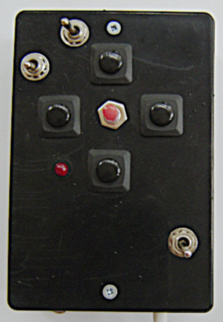
| The image opposite is the hand controller I came up with. The project box and switches etc you choose use are entirely up to you. I chose these because they are what I had to hand. If you don't want to get into PIC micro controller programming then I can supply the PIC's at £7.00 each fully programmed up. The price includes postage and packaging. Contact me at astro(dot)bloke(at)ntlworld(dot)com for more details. I have a pay pal account or I will accept a cheque. Alternatively you could get a friend to program you chip for free if they have a PIC programmer. |
What it does
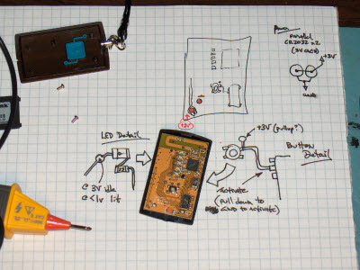
The image below shows the functions of the hand controller.
You are able to select the slew speed. These are faster than the standard hand controller. The source code is available if you want to change this speed. If you ask nicely I might provide a second HEX file with a different slew rate for the switch positions. There are Slew buttons provided for each direction and also a stop button which will stop the RA drive.
I have also provided two switches to swap the directions of the slew buttons. One for DEC and one for RA. These are useful if, for example, you swap from using an eyepiece to webcam imaging, flick the switches and the buttons move the object in the direction you expect. It also allows you to use the controller either way up according to your preference. Please note that the RA direction switch does not affect the RA drive direction.

The Circuit
I decided at the beginning to use two PIC's. One for the RA drive and one for the DEC drive. The main reason for this was that the RA drive timing has to be accurate. If I have to start running DEC code on the same Chip as the RA drive, it would be very difficult to keep the timing right. Over and above this, there simply aren't enough in/out pins to go around on a PIC16F627.
Here is the circuit diagram.
I've split the diagram into three parts, hopefully that way it is easier to read.
The RA Drive, the power supply and the
DEC drive.
The RA drive circuit and the DEC drive circuit are essentially the same. However the DEC circuit omits the crystal oscillator. This is because timing isn't critical for the DEC drive, I've used the PIC's internal 4MHz oscillator instead. Note: that the internal oscillator of the PIC16F627A is also 4MHz.
The DEC circuit also omits the indicator LED.
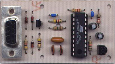
The basic circuit consists of the PIC micro controller and a L293D which is an H-bridge driver. There are very few extra components needed for the circuit to work.
How it works
The stepper motors supplied with the EQ-5 drive are bipolar. This means that they have 4 wires connected to two coils. To drive the motor, step by step the coils have to be exited in the right order. For a bipolar motor this involves reversing the voltage across each coil in the correct order. Rather than me reinvent the wheel, take a look at this document for the L297 stepper driver for more information about how this is done. To reverse the voltage across the coils requires a circuit called an H bridge driver. Fortunately for me there is a relatively simple H bridge driver readily available in the form of the L293D. The L293D documentation is available here. The L293D has 6 inputs, 4 are the logic inputs that determine how the coils are driven and the other 2 determine whether the coils receive any current at all. They are the enable inputs. Enable 1 is associated with inputs 1 and 2. Enable 2 is associated with inputs 3 and 4. Also make sure you get the D version. This has diodes that route the back EMF from the motor coils safely away from the sensitive electronics of the chip. without these you would need to add the diodes to the circuit.
The PIC micro controller is used to supply the correct logic to the six inputs to the L293D, to drive the stepper motor at the correct rate.
The Logic
There are three ways to drive a bipolar stepper motor. They are shown below.
Two Phase drive: All the coils are always enabled. This is the method I initially chose to use, I've since produced a half step version of the code. Two phase has the advantage of the simplest logic because the enable is always, err... enabled. It also provides the highest torque for the motor. The disadvantage is that it uses more power and runs the battery down more quickly.
|
|
Wave Drive: This method only energises one coil at a time. It creates less torque than the two phase method, the advantage being that it also uses less power so you batteries last longer.
|
|
Half Step: This is a combination of the Two Phase and Wave Drive methods. It doubles the number of steps by halving the distance the motor travels per step. The advantage is that the motor turns in a less jumpy manner. This ia a good way to run at the RA drive rate. I have now implemented this in code. The RA rate uses half step, while the slewing uses two phase. It also uses a little less power than the Two Phase method without any major sacrifice to torque.
|
|
The Circuit board.
The diagram below shows how I wired up the circuit onto veroboard. Be careful to note the orientation of the chips. I also went a little overboard with the 0v to the L293D, you may omit, if you wish some of those links.
The Yellow circles are external connections to the circuit board.
- Numbered circles are switch connections
- "L" is the LED connections.
- "A - A" and "B - B" are the connections to the stepper motor coils.
- "+" & "-" are the power connections.
The code.
The only thing missing now is the code. Well here it is. I have included the hex files needed to program the chips and the source code if you want to have a go at modifying the code for your own purpose.
Hex Code...
Click here for the RAdrive Code HEX file. (Northern Hemisphere)
Click here for the RAdrive Code HEX file. (Southern Hemisphere)
Click here for the RAHalfdrive Code HEX file. (Northern Hemisphere - Half Drive)
Click here for the RAHalfdrive Code HEX file. (Southern Hemisphere - Half Drive)
Click here for the DECdrive code HEX file.
Source Code...
Click here for the RAdrive source code TXT file. (Northern Hemisphere)
Click here for the RAdrive source code TXT file. (Southern Hemisphere)
Click here for the RAHalfdrive source code TXT file. (Northern Hemisphere - Half Drive)
Click here for the RAHalfdrive source code TXT file. (Southern Hemisphere - Half Drive)
Click here for the DECdrive source code TXT file.
If you do make an improvement to the code, send it to me and I'll feature it here.
the address is astro(dot)bloke(at)ntlworld(dot)com
You should now have enough information to make the controller. As added information I have also included some images of my controller in the hope that this will also help you. Note: I used CAT5 cable and then split the cables to the steppers from an RJ45 connector. This allows me to work from further away from the telescope.


Subscribe to:
Posts (Atom)


