
I recently arrived in Malaysia for a one month holiday that my girlfriend and I booked early in 2008. It has been quite hot and very humid since we arrived. So far, we've visited some of Kuala Lumpur and Petaling Jaya, and are about to head out to Kuching, in Sarawak, on the island of Borneo.
Some of the pictures of my journey so far are online here: http://www.flickr.com/photos/28808691@N05
20090130
20090127
Mengenal ADC (2)

Output dari sensor kita hubungkan dengan PORTA.0 (chanel ADC 0). Untuk kodenya kita gunakan aja CodeWizard agar lebih efisien n kita gak usah pusing2 hafalin register2 AVR.
Oke sekarang langsung aja:
1. klik icon CodeWizard di CodeVision AVR. Lalu klik tab ADC 
2. Pada tampilan tab ADC, centang ADC ENABLED utk mengaktifkan ADC
Use 8 Bits: untuk memilih apakah ADC menggunakan resolusi 10 bit atau 8 bit. Biarkan kosong(jangan di centang) agar ADC menggunakan resolusi 10 bit.
ADC Interrupt: Interrupt ADC diaktifkan apa tidak.
High Speed: mode high speed digunakan apa tidak.
Volt. Ref: referensi tegangan ADC. ubah ke AVCC pin, agar ADC menggunakan referensi teg. 5 volt.
ADC Clock: untuk memilih frekuensi clock ADC.
Ada pertanyaan menarik dari Mas HaPE, tentang ADC Clok ini:
di keterangan Clok ADC memang tertulis 125.000 kHz.
Itu bukan 125ribu kHz (125Mhz)
Tapi 125,000 kHz (125,0 kHz)
Inget orang Inggris nulis koma pake titik.
Auto Trigger Source: untuk menentukan sumber trigger ADC
...Ok let's finish this thing....
3. sekarang tinggal klik File ---> Generate, Save and Exit

lalu kasih nama dan simpen File2nya.
Contoh program ADC untuk LM35 :
#include <mega8535.h>
#include <stdio.h>.
#include <delay.h>// Alphanumeric LCD Module functions
#asm
.equ __lcd_port=0x18
#endasm
#include <lcd.h>#define heater PORTB.0//heater di hubungkan dg PORTB.0
#define ADC_VREF_TYPE 0x40
unsigned int read_adc(unsigned char adc_input)
{
ADMUX=adc_input|ADC_VREF_TYPE;
ADCSRA|=0x40;
delay_us(10);
while ((ADCSRA & 0x10)==0);
ADCSRA|=0x10;
return ADCW;
}unsigned char buff[33];
void lcd_putint(unsigned int dat)
{
sprintf(buff,"%d ",dat);
lcd_puts(buff);
}void main(void)
{unsigned int suhu;
float adc;DDRB=0xff;
PORTB=0x00;// ADC initialization
// ADC Clock frequency: 125.000 kHz
// ADC Voltage Reference: AVCC pin
// ADC High Speed Mode: Off
// ADC Auto Trigger Source: None
ADMUX=ADC_VREF_TYPE;
ADCSRA=0x85;
SFIOR&=0xEF;// LCD module initialization
lcd_init(16);while (1)
{
// Place your code here
adc = read_adc(0);
adc=adc/255;
suhu=adc*175;
suhu=suhu-12;
if (suhu<27)heater=1;
if (suhu>32)heater=0;
lcd_putsf("Suhu= ");
lcd_putint(suhu);
delay_ms(1000);
lcd_clear();};
}
Program diatas untuk membaca nilai suhu dari sensor LM35 trus hasilnya digunakan sebagai acuan untuk menyalakan Heater yg terhubung ke PORTB.0
Dalam program diatas terdapat code:
adc=adc/255;
suhu=adc*175;
suhu=suhu-12;
Fungsi kode diatas untuk mengkalibrasi nilai ADC agar sesuai dengan suhu sebenarnya. Setiap rangkaian memiliki error yg berbeda-beda. jadi nilai untuk kalibrasi harus di sesuaikan.
any questions?? post comment on this blog: http:\\avrku.blogspot.com
or send email to: zigan@ymail.com
CodeVisionAVR C Compiler is copyright by Pavel Haiduc, HP InfoTech s.r.l.
AVR is a registered trademark of Atmel Corporation.
20090126
Impressive and Frightening
This is one of the most impressive (and frightening on several levels) pieces of engineering I've ever seen. When there exists a device that can turn a living tree into logs in under 15 seconds, it is no surprise that deforestation can be a problem. Fortunately, this appears to be a tree farm... for IKEA?
The unbridled and unapologetic efficiency by which this machine performs its function leaves a visceral sensation of both awe and horror. It is distrubingly animal-like. The fact the tree is mostly debarked by the time it hits the ground makes my jaw drop.
The unbridled and unapologetic efficiency by which this machine performs its function leaves a visceral sensation of both awe and horror. It is distrubingly animal-like. The fact the tree is mostly debarked by the time it hits the ground makes my jaw drop.
20090124
Surfboards and repairs
So I begun massing quite a collection of surfboards, the current total is up to 7. Many of them have requirred minor repairs and such. I really love retro surfboards, especially twin fins from 79-85 ish... maybe thats because of all my battles with the star system fins. Which btw I finally got a pair of fins that I will soon make molds of (keep checking back with the fin post). Anyways, heres some pictures of my boards.


 (in order from left to right)
Before repairs
After Repairs


All my boards!
 (in order from left to right)
CB Challenger III shaped by Dan Ollila 5'9" tri fin with Star system fins
Rusty C-5 Shaped by Bill Johnson 5'10" 5 fin
WRV 5'11"-ish twin fin with Star system fins
C.W. Surfboards 6' single fin
Timpone 6'4" glass on tri fin
San clemente Surf co 7'6" tri fin
8' Single fin
Surfboards and repairs
So I begun massing quite a collection of surfboards, the current total is up to 7. Many of them have requirred minor repairs and such. I really love retro surfboards, especially twin fins from 79-85 ish... maybe thats because of all my battles with the star system fins. Which btw I finally got a pair of fins that I will soon make molds of (keep checking back with the fin post). Anyways, heres some pictures of my boards.
(in order from left to right)
Before repairs
After Repairs
All my boards!
(in order from left to right)CB Challenger III shaped by Dan Ollila 5'9" tri fin with Star system fins
Rusty C-5 Shaped by Bill Johnson 5'10" 5 fin
WRV 5'11"-ish twin fin with Star system fins
C.W. Surfboards 6' single fin
Timpone 6'4" glass on tri fin
San clemente Surf co 7'6" tri fin
8' Single fin
20090112
Transistor array
I am looking for transistor arrays for my LED projects as I want to reduce number of components on board. After some searches, I have found that there are two candidates for current source and sink transistor arrays as the following:
UDN2981 : 8 channels high current source MAX 500mA
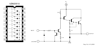
ULN2003 : 7 channels high current sink MAX 500mA
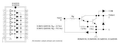
I will use these transistor arrays for driving large 7-segment display panel , bright led dot matrix panel and other LED projects.
UDN2981 : 8 channels high current source MAX 500mA
ULN2003 : 7 channels high current sink MAX 500mA
I will use these transistor arrays for driving large 7-segment display panel , bright led dot matrix panel and other LED projects.
20090111
Menghitung Resistor untuk LED

LED memang device kecil yg sepele, tapi kadang kita pusing saat mo nentuin resistor yang akan di seri ke LED untuk membatasi arus yang masuk. Karena bingung akhirnya maen comot aja nilai R nya, dan hasilnya nyala LED gak maksimal klo R nya ke besaren. Ato LED nya gampang meleduk klo R nya terlalu kecil.
Rumus menghitung nilai R untuk LED
R= V / I
Weheee.... sederhana kan... itu kan rumus dasar tegangan.
Nilai tegangan(V) adalah nilai tegangan sumber(Vs) dikurangi nilai tegangan LED(VL) (nilai tegangan LED diasumsikan 2,2 volt).
Arus yg boleh melewati LED kira-kira 20mA (0,02 A)
Jika tegangan sumber 12V besar VL nya adalah: 12-2,2 = 9.8 volt
R=9.8/ 0.02 = 490 ohm
Di pasaran sudah nyari R 490 ohm jadi kita nyari yang di atasnya dikit 510 ohm.
Setiap alat yang di aliri listrik pasti menimbulkan panas, begitu juga R yg kita gunakan ini. Semakin besar Daya maka panas yg dihasilkan juga semakin tinggi. So... kita harus memilih R dengan kapasitas daya yang sesuai agar R nya gak meleduk.. He3.....
P= V*I
So.... P= 9.8*0.02 = 0.196 watt
jadi minimal kita harus memilih LED yang 1/4 Watt (0.25 watt)
20090109
Sensitive Object - make any surface touch sensitive
This is not extremely new technology, but not a lot of people know about it and it has evolved quite nicely in recent years. Sensitive Object is a French company that sepecializes in the use of microphones to detect touches anywhere on an arbitrary objects. With multiple mics they can determine the location of touches or even dragging (as well as multiple dragging touches - not shown in the video below).
I've had a chance to play with it in person, and it's pretty impressive stuff. It works a lot better than I would expect. It doesn't detect touch locations using a triangulation technique (i.e. see how long it takes for the sound to reach each microphone) because that would vary greatly depending on the material the object was made of (plastic, metal, wood, etc) and depend on the shape of the object. Sensitive Object can do any shape like a vase, or statue.
They accomplish this using a pattern matching technique. Each touch sound gets compared to a known table of sound-to-location mappings. Which means you have to enter this mapping during a calibration step. (i.e. give the system a couple examples of touching each location that you want to recognize, touching here sounds like this.... touching there sounds like that). This upfront calibration step is somewhat heavy, but when you are done it's quite powerful. You could turn a cardboard box, a basketball, your car, or even your friend's head into a touch sensitive surface (if it's hard enough). Though, larger objects may only be "bang sensitive" surfaces.
20090108
Nintendo Game Shelf
Sorry its been a while since I posted... classes and work keep me occupied. I'm going to try and put up a few of my older projects soon, as well as the project I'm working on now for my new truck... and if it all goes well some updates to the surfboard fin post. So about a year ago I built a shelf with slots specially shaped to fit all the different nintendo cartridges, dvd cases, as well as a few other random game cartridges. I also made a chamber in the bottom with red rope light inside and put a plexiglass piece in front of it with the nintendo logo spray painted on it. I don't have any photos of the process, its pretty simple though. I still need to make wooden blocks for the N64 games so they don't slide too far back into the slots, I already made the SNES blocks.
20090104
A Simple Clock using DS1307 + PIC16F877A
Even I have posted about "DS1307 + PIC16F877A", I didn't have chance to make a real prototype of the clock. I have done only on the simulation software. Today, I have received a comment about that post. ah_bear followed my code and schematic on that post but the clock didn't work. This is because the code on that post is for reading time from DS1307 so there must be some values in the DS1307 before you can read. The solution is simple. Just place setting time codes before reading codes.
This time, I have made a real prototype to confirm that it's working. There is no setting buttons. If you want to make a real usable clock you have to implement the button interfaces (I may make one and post it here). The photo of my working prototype is featured below. Please check out my flikr at http://flickr.com/photos/punkky/ for more photos.
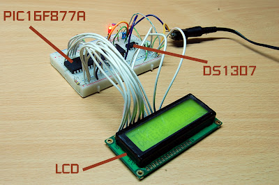
The schematic of the clock is very simple. Please note that the schematic does not show power supply to the PIC16F877A and the DS1307, you have to connect them by youself. If you are new to PIC/LCD interface please see MikroC "Hello World!" LCD example .

The source code:
This time, I have made a real prototype to confirm that it's working. There is no setting buttons. If you want to make a real usable clock you have to implement the button interfaces (I may make one and post it here). The photo of my working prototype is featured below. Please check out my flikr at http://flickr.com/photos/punkky/ for more photos.
The schematic of the clock is very simple. Please note that the schematic does not show power supply to the PIC16F877A and the DS1307, you have to connect them by youself. If you are new to PIC/LCD interface please see MikroC "Hello World!" LCD example .
The source code:
//Sample code for
//DS1307 RTC Interfacing with PIC16F877A
//Coded by punkky@gmail.com
//Compiler: mikroC 8.0.0
//http://picnote.blogspot.com
//05/01/2009
//Use with your own risk
unsigned short read_ds1307(unsigned short address );
void write_ds1307(unsigned short address,unsigned short w_data);
unsigned short sec;
unsigned short minute;
unsigned short hour;
unsigned short day;
unsigned short date;
unsigned short month;
unsigned short year;
unsigned short data;
char time[9];
char ddate[11];
unsigned char BCD2UpperCh(unsigned char bcd);
unsigned char BCD2LowerCh(unsigned char bcd);
void main(){
I2C_Init(100000); //DS1307 I2C is running at 100KHz
PORTB = 0;
TRISB = 0; // Configure PORTB as output
TRISC = 0xFF;
Lcd_Init(&PORTB); // Initialize LCD connected to PORTB
Lcd_Cmd(Lcd_CLEAR); // Clear display
Lcd_Cmd(Lcd_CURSOR_OFF); // Turn cursor off
Lcd_Out(1, 1, "TIME:");
Lcd_Out(2, 1, "DATE:");
//Set Time
write_ds1307(0,0x80); //Reset second to 0 sec. and stop Oscillator
write_ds1307(1,0x10); //write min 27
write_ds1307(2,0x01); //write hour 14
write_ds1307(3,0x02); //write day of week 2:Monday
write_ds1307(4,0x05); // write date 17
write_ds1307(5,0x01); // write month 6 June
write_ds1307(6,0x09); // write year 8 --> 2008
write_ds1307(7,0x10); //SQWE output at 1 Hz
write_ds1307(0,0x00); //Reset second to 0 sec. and start Oscillator
while(1)
{
sec=read_ds1307(0); // read second
minute=read_ds1307(1); // read minute
hour=read_ds1307(2); // read hour
day=read_ds1307(3); // read day
date=read_ds1307(4); // read date
month=read_ds1307(5); // read month
year=read_ds1307(6); // read year
time[0] = BCD2UpperCh(hour);
time[1] = BCD2LowerCh(hour);
time[2] = ':';
time[3] = BCD2UpperCh(minute);
time[4] = BCD2LowerCh(minute);
time[5] = ':';
time[6] = BCD2UpperCh(sec);
time[7] = BCD2LowerCh(sec);
time[8] = '\0';
ddate[0] = BCD2UpperCh(date);
ddate[1] = BCD2LowerCh(date);
ddate[2] ='/';
ddate[3] = BCD2UpperCh(month);
ddate[4] = BCD2LowerCh(month);
ddate[5] ='/';
ddate[6] = '2';
ddate[7] = '0';
ddate[8] = BCD2UpperCh(year);
ddate[9] = BCD2LowerCh(year);
ddate[10] = '\0';
Lcd_Out(1,6,time);
Lcd_Out(2,6,ddate);
Delay_ms(50);
}
}
unsigned short read_ds1307(unsigned short address)
{
I2C_Start();
I2C_Wr(0xd0); //address 0x68 followed by direction bit (0 for write, 1 for read) 0x68 followed by 0 --> 0xD0
I2C_Wr(address);
I2C_Repeated_Start();
I2C_Wr(0xd1); //0x68 followed by 1 --> 0xD1
data=I2C_Rd(0);
I2C_Stop();
return(data);
}
unsigned char BCD2UpperCh(unsigned char bcd)
{
return ((bcd >> 4) + '0');
}
unsigned char BCD2LowerCh(unsigned char bcd)
{
return ((bcd & 0x0F) + '0');
}
void write_ds1307(unsigned short address,unsigned short w_data)
{
I2C_Start(); // issue I2C start signal
//address 0x68 followed by direction bit (0 for write, 1 for read) 0x68 followed by 0 --> 0xD0
I2C_Wr(0xD0); // send byte via I2C (device address + W)
I2C_Wr(address); // send byte (address of DS1307 location)
I2C_Wr(w_data); // send data (data to be written)
I2C_Stop(); // issue I2C stop signal
}
20090102
360 Controller Mod


Here is a prototype button layout/cover just cut from a thin plastic lid like a pringles can. I used two layers, it gives you enough feel to find all the buttons. Pressing the upper layer has not caused any misfires on the other buttons. Now to make something nicer looking.

More info coming soon, I plan to put this on Instructables as well. I just need to drag my tripod out so I can take a few pictures that are not blurred.

I cannot take a good image unless I use a tripod, my natural shake is evident in most of these pictures (soldering was worse), this one below is no different. And it was the best of the many I took..oh well, you can see the copper trace exposed on SW14 near the bottom. This is where I soldered the switch leads, and since the controller uses a common ground, I soldered only one ground lead to the vibration motors terminal post. Just for the heck of it, I covered the switch pad with silicon glue to help stabilize the wires a bit.

My goal is to make a new set of buttons that will make sure when I hit the upper left portion of the dpad, I actually get that action. As you are aware with the current dpad you can shave away some of the plastic to make it work better, but you still do not get the accuracy of having eight individual buttons. I will paint the lexan cover plate to match the rest of the controller as best as I can. This will at least hide the ugly pcb board from Radio Shack.
I still need to fabricate a new set of buttons that will cover this, and currently I use a small piece of carbon fiber rod to hit the switch on the bottom layer. So far it works like it should, and in short testing it was 100% accurate.
I am using 6.5mm x 6.5mm x 5mm tact switches, a total of eight. Additionally, I have eight Schottky diodes on the bottom layer board to separate the diagonal (upper level) buttons from the main buttons. All the parts used were locally purchased, and so far my budget has been under $15. In the future I could order smaller switches off the internet, but for now I just wanted to make sure everything would work.
Additional images.


Subscribe to:
Comments (Atom)


