20091230

AVR Temperature Meter

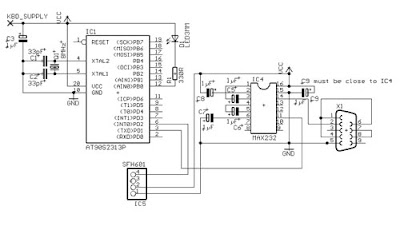
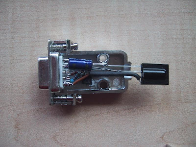
This is a four-channel temperature measurmet adapter that works without external power supply. It will suitable for measureing temperature and logging its data with a PC. The circuit diagram is very simple and no adjustment is required, everybody will able to build it with ease. These great project created by ChaN.

AVR Temperature Meter

"I chose an Atmel ATtiny15L for this project. It is the only device that has a built-in 10bit A-D converter in the 8 pin AVRs. The A-D converter has a bandgap reference and differencial amplifire as its front-end. The AVR core is clocked by only internal RC oscillator (calibrated to 1.6MHz), any other clock souce cannot be used. Also 25.6MHz clock source that 16x multiplied from core clock is available for timer/counter. This means that a fast PWM output can be generated. Therefore the ATtiny15L has good analog I/O capabiltity.

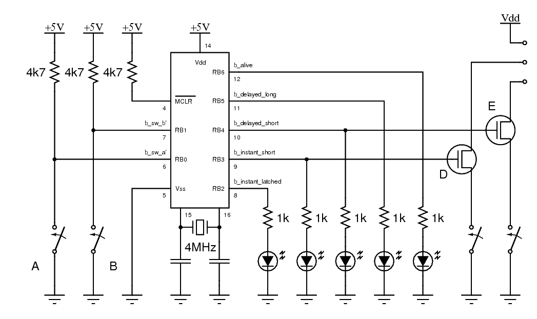
In this project, the A-D converter is used as four channels, single-ended, no gain and VREF from Vcc configuration. However RSTDISBL fuse must be programmed in order to use pin #1 as one of the analog inputs, an AVR programmer that can program in HVS mode is required."

For documentation, schematic dan code, download here


[link]

Simple Metronome Project

Simple Metronome ProjectDaniel designs this Metronome with a few simple electronic components.The Metronome is any device that produces a regulated audible and/or visual pulse, usually used to establish a steady beat, or tempo, measured in beats-per-minute (BPM) for the performance of musical compositions. It is an invaluable practice tool for musicians that goes back hundreds of years.


Material Needed:

Simple Metronome Project

1. 555 IC
2. 3x 1K Ohm Resistor
3. 2x 22uF 16V Capacitor
4. 9V Battery
5. 8 Ohms Speaker
6. 250K Ohms Potentiometer

[link]

20091229

Multifunction Digital Thermometer

Multifunction Digital ThermometerThis instructable will show you how to create a multifunction platform with a thermometer, chronograph (count up timer), count down timer, and light display. It is also intended to be a platform for other analog sensors or any other functions you can think of. Project is based on Atmega168 microcontroller. Information is displayed on dual 7 segment LED display.

Multifunction Digital Thermometer [link]

Serial interfacing LCD with PIC Microcontroller

Serial interfacing LCD with PIC MicrocontrollerParallel interfacing LCD with MCU at least need 6 I/O pins (4 bit mode) and maximun can up to 11 I/O pins (8 bit mode). The I/O pin can be cut down to 3 pin by serial iterfacing using shift register. They were few shift register can be used such as 74HC164, 74HC595, CD4094 and any compatible 8 bit shift register. Before you attempt to do serial interfacing, it is good pratice to familiar with parallel interfacing. You can find many reference from internet.Following diagram show the serial interfacing Hitachi compatible 2 X 16 LCD modules with Pic16F84 or Pic16F628 MCU.

Download documentation and source code for serial interfacing LCD with PIC here (zip file)
[link]

20091227

Atmega168 RDS decoder

Atmega168 RDS decoder
This decoder is fed by a RDS demodulator IC (or tuner) which has RDDA (data signal) and RDCL (clock signal) outputs.The microcontrolller is an Atmega168 clocked on the external 4.332MHz crystal from the RDS demodulator. TDA7330B RDS demodulator IC from STMicroelectronics to be used in this project. The TDA7330B is connected to the Atmega168 with RDDA connected to PD4 (on PORTD) and RDCL to INT0 (PD2).


The software in the Atmega168 is able to decode the following RDS data:

* Programme Identification code (PI: 0x83C7, Detected new station.)
* Program service name (PS: RADIO538)
* Programme Type code (PTY: 0x0A, Pop Music.)
* Traffic Programme Identification code & Traffic announcement code (TP&TA: 0x01 0x00, Traffic announcements available on this station and maybe via EON on another station.)
* Music Speech switch code (MS: 0x01, Music is being broadcasted or station does not use MS flag.)
* Decoder-identification control code (DI: 0x01, Stereo, Dynamic PTY.)
* Alternative frequency codes (AF: 0x98, 102.7MHz.)
* Linkage Actuator (LA: 0x00)
* Extended Country Code (ECC: 0xE3)
* RadioText (RTA: Radio 538 = Randstad (Zuid) 102.7 FM)
* Clock-time and date (CT: 0x1A53CD844, UTC 2006-07-02 (MJD 53918) 13:33:00 +02:00, TIME 15:33:00)

Download for document, source code here (zip)
[link]

Serial Port IR Receiver Using AVR

Serial Port IR Receiver Using AVRAnother cool microcontroller project created by Klaus Stock. He said, this is a simple IR receiver circuit which plugs into a serial port of a computer. This circuit has two major advantages:

1. it uses an Atmel AVR RISC microcontroller (an AT90S2313) instead of the usual PIC microcontroller and
2. it uses a Maxim MAX232 for the generation of valid RS232 levels.

Advantage 1 is, of course, only valid for all those AVR addicts which have this device (and the corresponding programmer) ready at hand and don't care about PICs and PIC programmers. Advantage 2 comes into play if the IR receiver has to placed at a great distance from the computer; the MAX232 is more likely to deliver valid signals over bigger distances than cheaper solutions.

[Link]

20091226

Digital Clock with PIC16F84A

Digital Clock with PIC16F84AThis is a small ajustable clock based on microcontroller PIC16F84A microchip.The electronic project here is very simple because the hardware only uses 74hct238 demultiplexer, 4x7 segments, and some resistors. The software is programmed through a device connected to serial port with icprog and made/debuged with MPlab. For PIC Programmer you can use JDM PIC16F84A programmer.

[link]

AVR Infrared Link Project

AVR Infrared Link ProjectThis AVR microcontroller project created by Sivan Toledo. In this project he created an infrared (IR) link that provides bi-directional communication between the NXT and the new Power-Functions system, which consists of a battery box, motors, a remote control (an IR transmitter) and an IR receiver that controls the motors.

He previously built an IR transmitter for the NXT which used an MSP430 microcontroller and which was able to send Sony IR commands. In this project, he wanted to achieve three additional goals:
  • To analyse the Power-Functions IR protocol.
  • To build a system that could not only send IR commands, but could also receive and decode them.
  • To experiment with AVR's, another family of microcontrollers.
But for this project he tried to use AVR Microcontroller. Compared to the MSP430 microcontrollers, the AVR family offers many more chips in DIP packages, they run at wider supply voltages (most can tolerate at least 2.7-5.5V and some operate down to 1.8V), and their pins can supply a lot of current (up to 40mA for a single pin). The wide range of supply voltages means that they can be connected to the 4.3V supply of the NXT's ports directly without a regulator, and the ability of the pins to supply a lot of current simplifies some circuits, such as when the chip needs to drive a bipolar transistor or a LED. Another advantage of the AVR is that they can be programmed using a wide variety of simple circuits, not just with proprietary programming devices.

[Link]

20091225

USB AVR Programmer STK500

USB AVR Programmer STK500In this microcontroller project, Guido Socher design a state of the art USB programmer for the AVR microcontrollers from Atmel. The programmer firmware has no device dependent data. Therefore it works for almost any AVR microcontroller on the market and possible future microcontrollers.

This USB programmer has, unlike other programmers, no "chicken and egg problem". That is: you can build it from scratch without the need of another programmer to load the initial firmware.The firmware is open source and programmed in C according to the AVR068 specification from Atmel.

[link]

Scroller 7 × 5 LEDs based on Attiny2313

Scroller 7 × 5 LEDs based on Attiny2313Cool microcontroller project from kalinda. In this project he used microcontroller AVR Attiny2313 that is perfect for controlling the 13 pins required for the matrix of LEDs. he has also provided pins in the most optimal order to occupy as little as possible.

List of materials

  • Programmer for AVR micros (AVRisp MKUII in my case)
  • Microcontroller Attiny2313 with fuses configured for internal oscillator 8Mhz
  • 1x Display 5 × 7 leds Kingbright
  • 1x voltage regulator 7805
  • 1x battery or source of food 9v
  • 2x Capacitors 100uF
  • 2x Capacitors 100nF
  • 5x Resistances 90 Ohms

Required Software

Drawings and plates

[link]

20091224

LCD SWR Meter using PIC 16F88

LCD SWR Meter using PIC 16F88Measuring SWR at VHF/UHF frequency was never a fun. Most radio amateurs just assume that their 50 ohms cable is matching a beam or GP.

LCD SWR Meter presented here meet many simple task using a microcontroller PIC16F88. The very basic purpose to make this project is to encourage radio amateurs to build their own High Quality LCD SWR Meter at low price, instead of buying expensive ready made units.

[link]

Measuring Heart Rate on LCD using PIC

Measuring Heart Rate on LCD using PIC Did you know that The human heart can be measured optically. The heart beat with the varying blood pressure leads to a measurable change in the visual content of peripheral blood vessels. This is as good at the finger detect. There are two project work available, which were so far advanced that the optical signal pulse seized on a liquid crystal display graphically. Both works have been with a microcontroller PIC16C74 to collect and visualization of the signals.

Pulse measurement in a light
The light source was a red LED superhelle. The finger penetrating light was a light-frequency converter TSL230 detected. The period of the signal from the TSL230 was using the capture of the micro-controller unit with an accuracy of about 15-bit recorded. Through digital filtering 50Hz interfering signals were suppressed and the pulse signal extracted.

Pulse measurement in reflection
For the lighting of the skin's surface, an infrared LED used. the censor use PIN photodiode. With an analog circuit filters were equal light and high frequency interference signals eliminated. The signal was pulse by the A / D converter of the microcontroller with 8-bit digitized.

[Link]

20091223

MJoy- USB video game controller

MJoy- USB video game controller
This microcontrller project build using micrcontroller AT mega 8 and Xtal 12 MHz as the clock source.
"If you like to play video games in your computer as much as I do, you probably already heard about the MJoy, which is an USB joystick made by Mindaugas that uses an ATmega8 and have 24 buttons, one hatswitch (or POV or D-Pad depending on the game) and 6 analog axes." said Raijuu.

More information about this microcontroller project check the source here.

LM75 Temperature Sensor with 7 segment display output

LM75 Temperature Sensor with 7 segment display output
This is a test project built hastily on a solderless breadboard. It uses a LM75 to read the current temperature via I2C and displays the result on three 7 segment displays. It uses a PIC16F628 with an internal 4 Mhz clock. The program was created using JAL

[link source]

20091222

AVR Internet communications device

AVR Internet communications device
If you looking for Microcontroller project that controlled via internet protocol, well this project could be your reference to build it. Internet0 is a electronic project by Neil Gershenfield, Raffi Krikorian and Dany Cohen. The concept is a new network of physical objectsthat are IP enabled. Any items we use in everyday life would have the ability to communicate in IP, and thus send data over the internet in a standardized manner, without considerable electronics or cost.

This microcontroller project using AVR ATmega8 programmed ini C. For display they use LCD HD44780.

The main elements of the project are:

Transmission
to send a UDP internet0 protocol. Implementation:
o A circuit board with a Tiny15
o Assembly code to send the protocol
o Lines for power and signal
o An LED to troubleshooting and to indicate transmission

Reception
Translate the clicks to bits

PC Communication:
A program in Python that receives information from the serial port and transmit this into the internet

Read more

USB AVR Programmer

USB AVR Programmer
Serasidis says "Nowadays, USB is the most popular connection connection between PC and peripherals such as AVR programmers, printers, scanners etc. For that reason I had to modify my old serial AVR In-System-Programmer (ISP) to work with USB connection. You can say, "use a USB to Serial adaptor to connect your AVR ISP with your PC". Yes, that could be a solution but it would cost me more money than a singe FT232BM chip because I had to include an USB to RS232 adaptor and a power supply for my programmer. (almost €30)".

So, the solution was to replace the two transistors, that were used to adapt the RS-232 voltage levels to TTL voltage levels, with a USB to RS-232 chip such as FT-232BM.

This programmer worked perfect with AVRprog (zip file) but it could work with AvrOspII V5.47 also.

Download the source code, firmware, programming software, schematic and PCB for this programmer here
[source]

20091221

Small TV Terminal AVR Project

Small TV Terminal AVR ProjectWhen you use microcontrollers in your designs, sometime you face a problem how to show user required data. Several LEDs, 7 segment display or LCD module can be solution. But if you must show a lot of information simultaneously, it can be difficulty. Large LCD modules are expensive and graphic modules require complicated control. You can solve it with a help of PC. Just send data via serial line to the computer and display everything on computer's display said Vassilis Serasidis.

This project created by Stan Pechal and he using AVR ATmeg8 as the main chip.

Want to try build this microcontroller project? download document, source code, sachematic here (zip file)
[source]

20091220

Windmeter using Microcontroller

Windmeter using Microcontroller The Windmeter is an anemometer designed to measure and record wind speed distribution from 0 to 17+ meters per second. It was designed for high reliability, ease of construction, and for a wide environmental range. Data is logged over a period of 30.46 days (1/12 of a year), and then saved for 11 months. The data can be retrieved with a laptop computer any time within the 12 months of logging. The Windmeter is self-powered by a solar pannel and battery. Calibration of the Windmeter can be done against a car's speedometer or better yet a GPS receiver. The Windmeter should cost you under $300 to make.

[source]

Flickr images on a Nokia LCD and AVR

Flickr images on a Nokia LCD and AVRAnother electronic project related to LCD. Alex has created microcontroller project : Flickr images on a Nokia LCD. The "brain" used microcontroller AVR ATmega48 and the software, he decided to fetch images from Flickr using Beej’s Python Flickr API.
Is it difficult to bulid this cool microcontroller project? well, if you follow what alex said i'm sure you can do it. May be i'll built it someday :)


20091219

PCB Drill Project

PCB Drill ProjectThis PCB drill project created by Shawn Kelly. This is one of cool electronic project. According to him, The moving part is the tabel not the drill head. To make sure everithing work fine, the project tested with Labcenter's Proteus VSM / Isis. With this PCB drill, it will saving our time to drill pcb when build electronic project.
[source]

PIC Universal Receiver Infrared

PIC Universal Receiver InfraredThe Universal Infrared Receiver (UIR) is a device that enables you to control your PC based application like PC home thaater with ANY remote controller you have (TV, VCR, CD or Stereo). Original hardware & software was designed by Martinus & Ties Bos. this projcet using microcontroller PIC12C508A.

PIC Universal Receiver Infrared schematicDownload
hex file

If you want build VCR without microcontroller you can try this schematic. To use it you need a plugin for Girder. I don't know if the plugin will work with other control software.


Universal Receiver Infrared without microcontroller[source]

20091218

Electronic Project : AVR Lux Meter

Electronic Project : AVR Lux MeterThe illumination is how the level of flows of light falling on a surface. . The flow of light is visible, which is defined in the flow (the light power) divided by relative sensitivity of the naked eye on the visible spectrum. This means that the Lux is well suited to the light level of meaning to the human eye. To measure the lighting, we can use Lux Meter.

We can build ourselves Lux meter using electronic components. At the detection of light we use photo diode. However, there is a difference between the spectra simple answer photo diode silicon and the naked eye, it can not be used for lux meter. Some photo diodes for lighting have a sensor compensation color filter on the window to correct its response spectra.

In this project, Photo-diode current results light that is well proportional to the light input power when used in short fashion. In this lux meters, the output current is converted into a voltage converter with an IV, he is caught by a micrcontroller AVR and displayed in terms of lux. The ppamp U1 in the circuit diagram that acts IV conversion circuit and its conversion becomes 50mV / μ A, in accordance with a record of comments R5. The capacitor C5 is to obtain the correction, it cancels Ct of the photo diode (about 200 pF). In this case, greater capacity in May rather be 220 pF because the high frequency signal is not necessary. The lux meter is powered by a 9V battery.

Download schematic, document, firmware (zip) here
[source]

Dot Matrix Project : Fancy Leds

Dot Matrix Project : Fancy LedsThe idea of this project came from Olivier de Broqueville's son. He was dreaming of a small tool able to write symbols or pictures on a screen. If using a graphic LCD, it was too expensive (or too easy?), so the solution adopted was to pilot a dot matrix of Leds. The Dot matrix project need only some cheap transistors, common red Leds, and a PIC microcontroller 16F628. And the dream could become reality.

Download for the document,source code, software and schematic here (zip file)
[source]

20091217

Project : Persistance-of-vision LED Sphere

Electronic Project : Persistance-of-vision LED SphereThe goal of this project was to develop 3D spinning mechanism capable of displaying smooth video or static images. The device uses a spinning ring with tri-color LEDs inside, and relies on precise angular sensing and persistance-of-vision and to create the effect of a spherical display surface. Although the system consists of only a single ring of LEDs, the high rotational speed makes it possible to display any combination of red, green, or blue pixels along the surface of the resulting sphere. (3-bit color depth!)
[source]

PIC Robotic Webcam

PIC Robotic WebcamMain parts to built PIC robotic webcam are two servo motors and microcontroller PIC. This eletronic project not too hard to build it if you have some electronic basic and programming the microcontroller. For the main processor this project utilized PIC 16F84. The total cost of the project is about 40 Euro (40$). All the software/code can be downloaded as free or shareware.

Download program and free servo controller here
[source]

20091216

PIC16F84 based Hexapod Robot

PIC16F84 based Hexapod Robot
This Hexapod Robot created by Mike Smyth. It uses 12 R/C servos for actuators. The 6 that raise and lower the legs are Hobbico CS-72 1/4 scale and the 6 that move the legs forward and backward are several brands of standard 1/10 scale servos (all are similar the Futaba S3003). The total robot weight is a little over 5lbs and the payload capacity is around 5lbs additional. The vertical travel of the legs is 1 7/8". Overall length and width is 13" X 11". When crouching, it's 5.5" tall. When standing up there is 3.5" of ground clearance under the body.


There are actually two PIC16F84's on the hexapod. The main processor contains all of the walking code and generates positioning pulses for all 12 servos. Twelve of the 13 I/O lines are used for switch inputs - one on the bottom of each foot and a contact sensor in the front of each leg. The servo pulses are output sequentially on the last I/O line. All the second processor does is de-multiplex the pulses from the main processor and send them to the appropriate servo

R/C Transmitter Range Tester

electronic circuit project - R/C Transmitter Range Tester
This project suitable for people who like with the transmitter system. It's an electronic analog project. You don't have to programming the IC to build it. The function of this electronic project is to measure the RF power being radiated from a transmitting antenna.

Among the Amateur Radio fraternity, a device such as the one described here would otherwise be known as a Field Strength Meter (FSM). Its main purpose would be to check that RF power is being radiated from a transmitting antenna. Some FSMs are tuneable across a wide range of frequencies, which allows the device to work with different transmitters and antennae - usually from HF to VHF and beyond. A difference with this unit is that it is only sensitive to those signals in the R/C section of the radio spectrum. The on-board trimmer allows you to tweak for maximum signal strength of your frequency of choice, whether it be 27MHz AM, or 40MHz FM.

In order to read the received signal strength, such a unit would ordinarily employ a mechanical analogue meter. The unit described here differs in that it uses four super-bright LEDs. The benefit of this is that it allows you to read the display from a distance - even in bright sunlight.

PIC Room Timer

Microcontroller project - PIC Room TimerThe purpose of this electronic project is to present a device that is useful and at the same time demonstrate to the beginner many features involved in programming the PIC. Some of the topics included are:

* Simple use of MPASM assembler
* Demonstration of use of timer 0 and the prescaler
* Use of length of instructions to set up timing delays
* Using interrupt routines
* Detection of switch closures including debouncing
* Saving and recovering data from the onboard EEPROM


Download the source code (.asm)

[source]

PIC Universal RC5/RC6 transceiver

PIC universal remote control projectThis is another Universal RC5/RC6 transceiver project. It use PIC16F628 as main processor. On the one side you can read the RC5, RC5X and RC6 codes from remote controls on a LCD and on the other hand you can send all thinkable RC5, RC5X and RC6 codes to a device.

20091215

AVR Shark Tag Project

microcontroller project animal tag

The goal of this project was to develop a shark tag working bench-top microcontroller platform. It is to be used for on-animal, in-situ data logging applications involving sharks and potentially other large pelagic.

The project used the Atmel Mega32 microcontroller to develop the core platform and functionality of a data archival tag. The project use temperature and pressure as sensor variable. The tasks ranged from logging sensor data to developing a simple user interface that requires only the addition of a laptop and a custom RS232 serial cable in the field.

It used an off-the-shelf SD (Secure Digital) card using flash memory for large capacity multi-read/write data storage. The microcontroller’s ADCs (analog to digital converters) were used to convert analog voltages produced by select sensors into digital format.

XBOX Controller

XBOX Controller Controller
What is this? It's a system that will allow basically anything that can talk udp to control an Xbox. Why would you want to do this? I have no idea. I have my reasons, maybe you have some too. How this works: The XBOX buttons are physically pressed by arms (stiff wire) attached to servos that are controlled by a Basic Stamp 2. The BS2 is controlled by a gumstix over a serial port. The gumstix talks udp and accepts commands. So if you want to control an xbox, you basically have to talk a simple udp protocol to the gumstix.

xbc-c-controller
For this I tried 2 controllers, a PSP and a Nintendo DS. The udp protocol is simple. Build a message with the status of your controller, and the system takes care of moving the physical fingers on the xbox controller. The protocol is as follows: '!!' for start of message, and '##' for end of message. The juice of the message is a 1 character button identifier, followed by a 1 byte state. 1 means the button is pressed and 0 means button is not pressed. Here is a sample message:

The message should be self explanatory. So the controller (in this case the psp or nds) polls inputs every so often and then dumps the state. I had it all working at every 100ms, but then something happened - not sure what - so I backed it down to every 250ms. The bottle neck is on the BS2, and to keep things consistant, I just kept all polling intervals the same.

The app on the gumstix consists of 2 threads. One listens for udp commands and the other babbles out the serial port at 38.4k. The serial thread wakes up every 250 ms and sends the status of all buttons to the BS2. The status is stored in global variables that are updated by the udp thread whenever the controller sends an update.

The serial protocol to the BS2 is simple. A 'A' signifies a start of message followed by 8 bytes of status for each of the buttons currently supported. The PIC decodes this message and tells the servos to respond accordingly.
xbc-c-pic.

MICRF102 Based RF data logger

Electronic Project : RF data loggerTelemetering is a methode to measure voltage, temperature or any other variable which long distance between censor and data processor. There are many ways to implement telemetering, one of them using wireless RF data logger. What do you need with this project is Rf transmitter, RF receiver and Data processor (PC) . Any number of these recorders transmits data packets to a central PC-based receiver. A PC program stores the information for later analysis.

The RF data logger project use small RF IC's the MICRF102 from Micrel because it's good compromize between price and complexity. The MICRF102 is a low power ASK transmitter IC. It generates UHF frequencies by PLL multiplying a crystal oscillator frequency by 32. In this case a 13,56MHz crystal provides a 433,925MHz carrier. The data recorder is controlled by a small AVR TINY45 microcontroller.

Download schematic RF transmitter (gif)
Download schematic RF receiver (gif)
[source]

PIC Microcontroller based Doorbell

Microcontroller project : doorbell
If you new in microcontroller project. May be you want to build just a simple electronic project. Like Doorbell created by Quozl. He used microcontroller PIC 16F84 for the main processor. I know that we can build simple doorbell without microcontroller. But, take a look the feature of this project.

A microcontroller driven doorbell circuit with features:

* one second instant pulse output,
* one second delayed pulse output,
* two minute lighting output,
* latching has been triggered indicator,
* processor alive indicator,
* ignore additional trigger for preset duration.

Do you want to build the project? Ok, here is the source code, schematic and the pcb.
source

20091214

Simple AVR Project : Battery Monitor

Simple AVR Battery MonitorBatwatch is a simple monitor for a solar panel battery charger, using an Atmel ATtiny13V. It periodically measures the charge current and battery voltage, and shows them by blinking two LEDs. I built this circuit into the plug of a VW solar charger panel that is used to prevent a discharge of the battery when a car is not used for some time. A modern car contains a large amount of electronics, and a quiescent current of 40-50mA (about 1Ah per day!) is considered "normal".

Download the batwatch project, schematic

PIC based RFID reader

microcontroller project : RFID reader based on PICRFID cards are commonly used for access control and bus/train tickets. They are convenient because no direct contact is required to transfer information to and from the card. The card itself is powered by the RFID reader, so there is no battery to change.

For the experiments, He use a HID ISOProx card. These cards are the simplest of all RFID cards as they only stores a single serial number and uses no encryption. The carrier frequency is 125 KHz. For processing the data, the project uses microcontroller PIC 16F628A.

Interesting to build it?

Download the schematic 1, schematic 2.

20091213

PICkit 2 Starter Kit


Features:
  • Low Pin Count demo board supporting 8/14/20-pin mid range PIC microcontrollers.
  • 20-pin PIC16F690 Midrange microcontroller. Note: Requires the AC162061 ICD Header and AC164110 adapter to debug.
  • A series of 12 Lessons on assembly programming that cover I/O, A/D converters, timers, interrupts, and data tables (All source code files are provided)
  • Getting Started in PICBASIC PRO tutorial on developing and debugging in BASIC with a FREE microEngineering Labs PICBASIC PRO™ Demo Compiler (contained on the PICkit 2 CD)
  • HI-TECH PICC™ LITE C Compiler with MPLAB IDE.
MPLAB Integrated Development Environment (IDE) is a free, integrated toolset for the development of embedded applications employing Microchip's PIC and dsPIC microcontrollers. MPLAB IDE runs as a 32-bit application on MS Windows, is easy to use and includes a host of free software components for fast application development and super-charged debugging. MPLAB IDE also serves as a single, unified graphical user interface for additional Microchip and third party software and hardware development tools. Moving between tools is a snap, and upgrading from the free software simulator to hardware debug and programming tools is done in a flash because MPLAB IDE has the same user interface for all tools.

Energy Efficient AMD Processors Reach Retail


AMD announced that their new Athlon processors were built for energy efficiecy. AMD said the processors would cut the power requirements of desktop processors by over one-third, boosting the performance-per-watt process. Basically, the processors will reduce power consumption in active and idle states. We featured AMD previously for their green energy initatives, and because they are reducing the lead contained in their chips.

Now, the new AMD processors, the Athlon 64, Athlon 64 X2 and Sempron processors are currently available in several stores in Japan.

A number of stores in Japan have begun to sell energy efficient versions of AMD Athlon 64 X2 3800+ and 4200+ models, which consume 65W, down from typical 89W thermal design power (TDP).

In terms of energy consumption, laptop computers consume much less power, and they run on DC voltage — an advantage for off-grid users.

Continuous Microchips Glucose Monitoring Shows Promise


Popular Science is reporting on the work of MicroCHIPS, a Bedford, Massachusetts firm that's designing under-skin implantable devices to measure chemicals and deliver drugs. The exciting news is that the firm will be performing clinical trials next year on its glucose detecting microchip, a device that has apparently shown positive results when studied on animals.

From the company technology page:

MicroCHIPS' technology is based on proprietary reservoir arrays that are used to store and protect chemical sensors or potent drugs within the body for long periods of time. These arrays are designed for compatibility with preprogrammed microprocessors, wireless telemetry, or sensor feedback loops to provide active control. Individual device reservoirs can be opened on demand or on a predetermined schedule to precisely control drug release or sensor activation.

Our reservoir-based platform can also be used in passive control systems without microprocessors or power sources. MicroCHIPS' passive systems are designed to release or expose their contents based on the controlled degradation of polymeric matrices over time. These systems form the basis for miniature insertable devices that provide maximum flexibility for device placement.

Samsung ships 8GB microchips

Memory is getting smaller and smaller by the month. Samsung has announced shipment of 8GB microcards that can be used in portable devices such as cellphones and even in external memory adapters for a huge boost in storage. The day will come when traditional portable HDs will be phased out in favor of the more versatile flash drives which you can use anywhere - since there are no moving parts.

PIC Project : Infra/radio remote control transmitter/receiver

PIC Project : Infra/radio remote control transmitter/receiverThis is a general purpose remote control project with programmable PIC microcontrollers. Schematics are shown for using infrared (RF) or radio (RF) media. If you are not familiar with microcontroller programming, you can use fixed encoder and decoder integrated circuits instead. Well-known such IC-s are Holtek HT-12D, HT-12E and Motorola MC145026, MC145027, MC145028.

Remote controls usually consist of encoder/decoder parts connected to a transmitter/receiver module which takes care of the transmission of digital signals by radio or infra waves. The format of this project's signal is designed to be ideal even for the cheapest ASK RF modules (using 50% signal/silence ratio), and it is similar to the Philips RC-5 format used in infrared remote controls. The transmitter has a varying number of buttons and sends the states of these inputs to the receiver. The receiver device decodes the message and sets the outputs accordingly.

Download : schematic IR(jpeg), schematic RF
source

search term : PIC microcontroller project, Infra Radio Remote controll, Trnsmitter and receiver project

PIC Project : Alarm Security System

PIC Project : Alarm Security SystemThis Alarm Sytem is based on two PIC12C508 (one is used in transmitter and the other one in the main unit). The following PICs are supported: 12c508, 12c509, 12c508a, 12c509a, 12ce518, 12ce519, 12f508, 12f509, 16f84 and 16f84a. Transmitter uses infra red beam to send code name to main unit. The commands are:

* Arm/Disarm
* Silent Arm/Disarm
* Weak battery in transmitter

It implements the folowing features:

* IR remote keyless system
* 72 bits transmission length (64bits password, 4bit CRC, and 4bits for commands)
* Arm/Disarm
* Immobilizer
* Two stage sensors, door and shock sensor trigger inputs
* Locking/unlocking of doors
* Normal/Silent modes
* Inside zone intrusion memory
* Transmitter low battery indication

This system is a perfect solution for unidirectional remote keyless entry systems and access control systems. Such system may be implemented in:

* Automotive alarm systems
* Automotive immobilizers
* Gate and garage door openers
* Burglar alarm systems

Download :
Here you can find transmitter assembler code (updated on March 11, 2008) and a password.inc file. Don't forget to change processor type in MPLAB or you will get errors. I've added PIC16F84 family processors for debug. And also you can find main unit assembler code.

Schematic :
Download Transmitter schematic, main unit schematic, IR Receiver schematic, IR Receiver Schematic Diagram (TBA2800 Based)
src

20091212

Electronic Project : Simple IR (Infra Red) Receiver

Electronic  Project : Simple IR (Infra Red) ReceiverI guess this is the simplest IR receiver circuit i ever know. It's only use few pasive component and TSOP 1738 IR receiver that housing on Sub-D 9-pin serial box.

Simple IR (Infra Red) Receiver Schematic
tags : IR Receiver, simple electronic project, digital project link

Traffic Light Control Circuit

Electronic Project - Traffic Light Control CircuitThis electronic project based only on 74LSxx family and IC 555 as clock source. It's a digital logic circuit. To build Traffic Light Control you don't need microcontroller programming.

This page features a circuit that has twenty open collector outputs that turn on one at a time in a continuous sequential manner. The circuit make use of the 74LSxx family of TTL integrated logic devices. The circuits are designed to drive light emitting diodes or low current, low voltage incandescent lights but can also drive other loads of up to 80 milliamps.

download :
schematic

tags : traffic light circuit, digital logic circuit, electronic project link

20091211

PIC Autorange Capacitance Meter

PIC Autorange Capacitance Meter
This electronic project is really powerful capacitance meter. This is an autoranged Capacitance Meter version, which means one does not need to adjust the range settings. Furthermore, the measuring range is quite large, from 5pF all the way to 2600uF. It is all taken care of by the PIC16F873A inside the circuit.

It is based on a very simple circuit analysis principle of charging and discharging of capacitors in an RC circuit.

download : schematic and source code

Capacitacance Meter, Metering Circuit, microcontroller PIC Project link